My version is based on the version from Phil Warner
My build is slightly different, I use the arduino to control the servo’s directly without the servo controller.
The software is written by me, this is because I use another interface and wanted to find out how to get it working on my own.
The photo’s are also on flickr over here
I’ve split the page into multiple pages , below are the links..
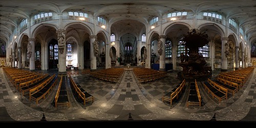
My first big photo shot at 24mm with a total off 44 photo’s.
Robin,
Do you have any problems mounting the pan servo to a tripod? Or have you added an extra bracket for support?
Also, do you have any recommendations that would simplify Phil Warner’s design? I don’t have access to a tube bender or 1/4 inch pipe tap.
Ken,
The mount was very simple using a Manfrotto plate, there are now some pictures at the top.
I also had some problems getting a tube bender and looked at the square aluminium profiles and used this on my very first experimental version. I cut out a V shape and bended it to 90 degrees and used a small aluminium piece to make ik more stable..
This version never made it to any photo’s because I mounted the servo’s wrong several times and it was full off holes
Than I found a local company which rents out tools for a day..
Thanks. That mount is exactly what I was missing. Now that you have the device done would you use the original square aluminum? That was the same idea I had because it is probably thicker aluminum.
I was thinking of using the simple bracket system from http://www.lynxmotion.com. They have Aluminum Large (1/4 scale) servo brackets that can be used to produce a two axis movement. This is a sample of how they connect the servo’s: http://www.lynxmotion.com/Product.aspx?productID=288. These are the standard bracket version.
I’ve noticed that almost all the servo pan/tilt solutions online use the servocity servo power gearbox. I don’t think panning requires the amount of torque the gearboxes offer. But you do get more granularity the higher the ratio, so you can control the degrees of movement with more accuracy.
I have a canon 40d that weighs in at about 4 lbs.
-Ken
I switched to the aluminium tube because it was easier to make and replace and the total weight is smaller..
The best way to make the panorama is turning the camera around the optical center off the lens, I think the small servobrackets without gears are not strong enough to lift the camera..
The servocity servos also give two ballbearings and can support a load off 200 lbs sideways. I killed the first servo internal gears which I used to for the panning because off the weigth.
The bottom gearbox gives me 1300 values/steps to make a complete 360 turn in 7 seconds, it can make two full turns.
The other servo uses 2240 values/steps to make a complete turn (11 sec) but I use a maximum of 180 degrees, it can make one and a half turns.
I just shot a film off the device shooting two panorama’s , first a single row and second a full panorma.. (link up in the text)
Thanks for posting your arduino code. It will be an improvement to what I use if I make a new controller.
I’d like to upgrade my panobot to where the gear slop was removed form the panning axis. I see your panobot has the same issue. One thing that helps a little is to code in a soft start up and stop on the panning movements. Some type of break, magnetic(?), would be ideal.
Phil
Hoi Robin,
Mooi project, en super resultaten.
Ik ben zelf nog maar net bezig met fotografie en geïntereseert in panorama fotografie.
Ik wil graag met een collega van mij een microcontroler gestuurde panoramakop bouwen en ik denk dat de constructie met de modelbouw servo’s wel interesant kan zijn.
Hoe stuur je de servo’s aan?
Mijn kennis van electronica is nog niet zo goed dat ik de bestuuring op eigen houtje zou kunnen ontwerpen, zou jij ons de schema’s van jou bestuuring willen aanleveren?
Bij voorbaat dank,
John
Ik heb niet echt schema’s , alles is in kleine stapjes steeds verder uitgebouwd.
Ik haal steeds uit de software wat nu waarop zit aangesloten.
Ik stuur de servo’s rechtstreeks aan met de arduino, na het uitzoeken hoe de timing werkte is dit eigenlijk heel simpel te doen. Er zijn twee pinnen die hiervoor gebruikt kunnen worden een derde kan met pwm worden aangestuurd maar hebben niet dezelfde stap resolutie.
De enige beperking met servo’s is dat je een positie opgeeft en daarna moet wachten tot de servo op die positie is dit zorgt voor extra wachttijd. Maar het grote voordeel is dat ze eenvoudig aan te sturen zijn..
Ik gebruik de volgende dingen;
– servos : zitten direct op een arduino pin.(9,10 en de lock op 11)
– Trigger/focus : Beide met een 4N35 met een voorschakel weerstand van 330 ohm direct op een arduino pin
– power relais : Reed relais 5V zit ook direct naar een pin
– LCD display : I2C display , gebruikt maar 2 draden en direct vanuit de arduino aan te sturen, heb geen weerstanden gebruikt zoals hier en daar aangeraden.
– knopjes : zitten ook direct op een eigen pin met een pull-up weerstand van 2k2
Bijna alles is terug te vinden als je het in losse onderdelen op het internet zoekt, knoppen/display/servos
Als ik de controller binnenkort weer eens open heb zal ik proberen een tekeningentje te maken..
Robin..
Hoi Robin,
Bedankt voor je reactie.
Ik heb me gister avond wat meer ingelezen in de arduino, en er gelijk 1 besteld om es mee te experimenteren.
Het is echt een heel handig printje.
Ik verwacht dat ik wel een heel eind komen met alle info die ik op het web vind.
Ik zal je een beetje op de hoogte houden van onze vorderingen en hoe wij het apparaat bouwen.
Nogmaals bedankt.
Gr. John
Hi,
I’m thinking of making something like this, I know one of the circuit boards is an Arduino, what is the second circuit board in the casing?
Chris
The board below the arduino is the Lithium Backpack, I use the ‘raw’ output to power the servers because the board can not deliver the 5v to drive all hardware.
The board next to at the bottom is for the relays (servo’s on/off) and the camera triggers (2N35) the other board is from the I2C display module..
I added a descriptions to this flickr photo